Linear Momentum: Interactive Simulation
This simulation was prepared using Mathematica. Download the free Wolfram player, and then download the simulation CDF file (link given below or click on figure to download).
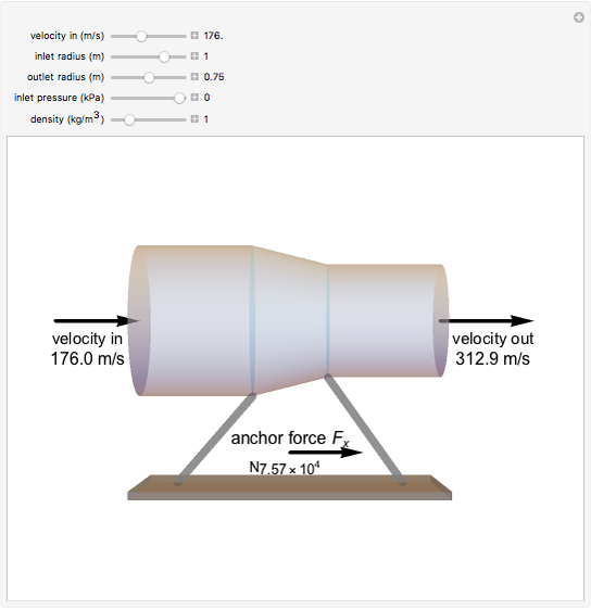
The force generated by a jet engine on a static thrust stand can be determined using Newton’s second law of motion, in which the time rate of change of the linear momentum of the system is equal to the sum of external forces acting on the system. For a fixed, nondeforming control volume with uniform and steady flow, the sum of the forces is equal to the net rate of linear momentum flow through each control surface. This simulation illustrates the effects of air density, intake velocity and pressure, and control surface areas on the resultant anchoring force (Fx) necessary to hold the jet engine stationary.
Try to answer these questions before determining the answer with the simulation. We suggest that you write down the reasons for your answers.
- What happens to the anchor force when the inlet radius is decreased? Does it increase, decrease, or stay the same?
- What happens to the anchor force when the density is increased? Does it increase, decrease, or stay the same?
- Review the parameters shown in the sliders below. Show that the velocity out is equal to 312.9 m/s. Then use the linear momentum equation to show that the anchoring force is equal to 75,700 N. Be careful with your signs, and clearly demonstrate that the anchoring force is positive (acting to the right).
- For the parameters shown in the sliders below, the anchoring force acts to the right. Why is this so? Because this is a jet engine that is trying to fly the airplane to the left, it is tempting to say that the force is to the left. Why is this not the case?


