Forces in a Power Tower Truss


Description
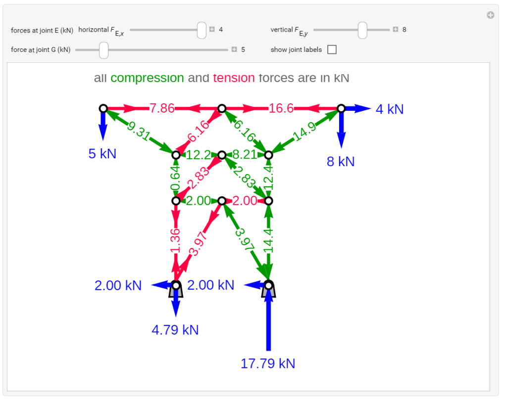
The method of joints is used to solve for the member forces and reaction forces on a power tower truss. Use sliders to set the point load forces at joints G and E, and check “show joint labels” to see the labeled joints. This truss rests on two pinned supports, which resist both vertical and horizontal forces. Member forces are shown in kN. Arrows that point outward (green) represent the member response to compression forces, and arrows that point inward (red) represent the member response to tension forces. Compression acts to shorten the member and tension acts to lengthen it. Zero members (black lines) are in neither tension nor compression, so their force is 0 kN. Zero members provide stability and extra support to the structure in case another member fails.
About
This simulation was made at the University of Colorado Boulder, Department of Chemical and Biological Engineering. Author: Rachael L. Baumann
View the source code for this simulation


