Solid-Solid-Liquid Phase Diagrams: Interactive Simulations
These simulations were prepared using Mathematica. Download the free Wolfram player, and then download the simulation CDF file (link given below or click on figure to download). Try to predict the behavior when a parameter changes before using a slider to change that parameter. Screencasts below explain how to use these simulations.
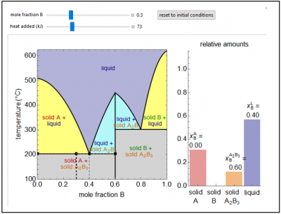
This Demonstration shows a solid-liquid phase diagram for two elements (A and B) that also form a solid compound (A2B3); neither element A or element B is miscible in the solid phase. The amounts of each phase (solid A, solid B, compound A2B3, and a liquid phase containing A and B) are shown in the bar graph on the right. The system contains one mole total. The mole fraction of B in the liquid phase is given on the liquid bar. Change the overall mole fraction of B with the slider. Change the temperature by using the “heat added” slider, although when the black point is on the horizontal lines at 200°C and 300°C, the temperature will not change until one solid phase melts (adding heat) or the liquid phase solidifies (removing heat). The amounts of each phase present are determined from mass balances. The amount of heat added is not meant to represent the value for a real system.
Try to answer these questions before determining the answer with the simulation. We suggest that you write down the reasons for your answers.
- At what temperatures can heat be added without a change in temperature for the binary phase diagram in the figure below?
- If a one mole of the binary mixture represented by the diagram below is at 300 K and a mole fraction of B of 0.1 is compared to a one mole at 300 K and a mole fraction of 0.2, which composition has the higher energy or are the energies equal?
This simulation was prepared by Lisa M. Goss and is located here. Open content licensed under CC BY-NC-SA.
A solid-liquid phase diagram for the uranium-titanium system shows the regions of phase stability as a function of the temperature and overall composition of the system. The phases are (1) a liquid mixture of uranium and titanium of variable composition, (2) solid uranium U(s), (3) solid titanium Ti(s), and (4) a solid phase compound with the formula TiU2(s). In this phase diagram, the phase boundaries are shown as solid black lines. The phase boundaries involving liquids are assumed to be a linear function of composition. When the temperature and composition are at a point above all the phase boundaries, only the liquid mixture is stable. At any point inside the phase boundaries, two phases are stable. The phases present, as well as their relative amounts, are shown in the bar graph on the right. When the liquid phase is present, its composition is found by drawing a horizontal line (here shown as a dashed red line) to the appropriate phase boundary. For a solid phase, a horizontal line is drawn (here shown dashed) to the vertical phase boundary corresponding to the pure solid. These horizontal lines are called “tie lines” or “levers”. The lever rule is used to calculate the relative amounts of the two phases, which are shown on the bar graph on the right. The composition of the liquid phase is indicated by the red dotted line and numerically at the top of the bar graph.
Try to answer these questions before determining the answer with the simulation. We suggest that you write down the reasons for your answers.
- How many separate regions on the Ti-U phase diagram below have two phases in equilibrium?
- For the black point in the figure below, if the temperature increased, what would happen?


